Level 2: Introduction to IoT
Introduction to ESP8266 and ESP32
ESP8266 and ESP32 are cheap Wi-Fi modules and are mostly used in the projects of internet of things. We can easily control and monitor remotely via Wi-Fi. ESP32 is successor of ESP8266. ESP8266 is also known as NodeMCU (Node MicroController Unit). NodeMCU is an open-source software and hardware development environment built around an inexpensive System-on-a-Chip (SoC) called the ESP8266. The ESP8266, designed and manufactured by Espressif Systems, contains the crucial elements of a computer: CPU, RAM, networking (WiFi), and even a modern operating system and SDK. That makes it an excellent choice for Internet of Things (IoT) projects of all kinds. The ESP32 is loaded with lots of new features. The most relevant: it combines WiFi and Bluetooth wireless capabilities and it’s dual core.
Both boards are programmed with the Arduino IDE which is an advantage for those who can understand Arduino. Both are compatible with same library and commands. Some libraries are only compatible with the ESP32 or ESP8266 and will not run on both modules. However you need just few modifications.
Difference between NodeMCU and ESP32
| SPECIFICATION | ESP8266 | ESP32 |
|---|---|---|
| MCU | Xtensa Single-core 32-bit L106 | Xtensa Dual-Core 32-bit LX6 with 600 DMIPS |
| 802.11 b/g/n Wi-Fi | YES,HT20 | YES,HT40 |
| ADC | 10-bit | 12-bit |
| Hardware/Software PWM | None / 8 Channels | 1/16 channel |
| Typical Frequency | 80MHz | 160MHz |
| SRAM | 160kBytes | 512kBytes |
| GPIO | 17 | 36 |
| Touch Sensor | NONE | YES |
| Bluetooth | none | Bluetooth 4.2 |
| SPI/I2C/I2S/UART | 2/1/2/2 | 4/2/2/3 |
| ADC | 10-bit | 12-bit |
| CAN | NONE | 1 |
| ROM | No Programmable | 448kB of ROM for booting and core functions |
| Working Temperature | -40°C to 125°C | -40°C to 125°C |
Datasheet
ESP8266

ESP32
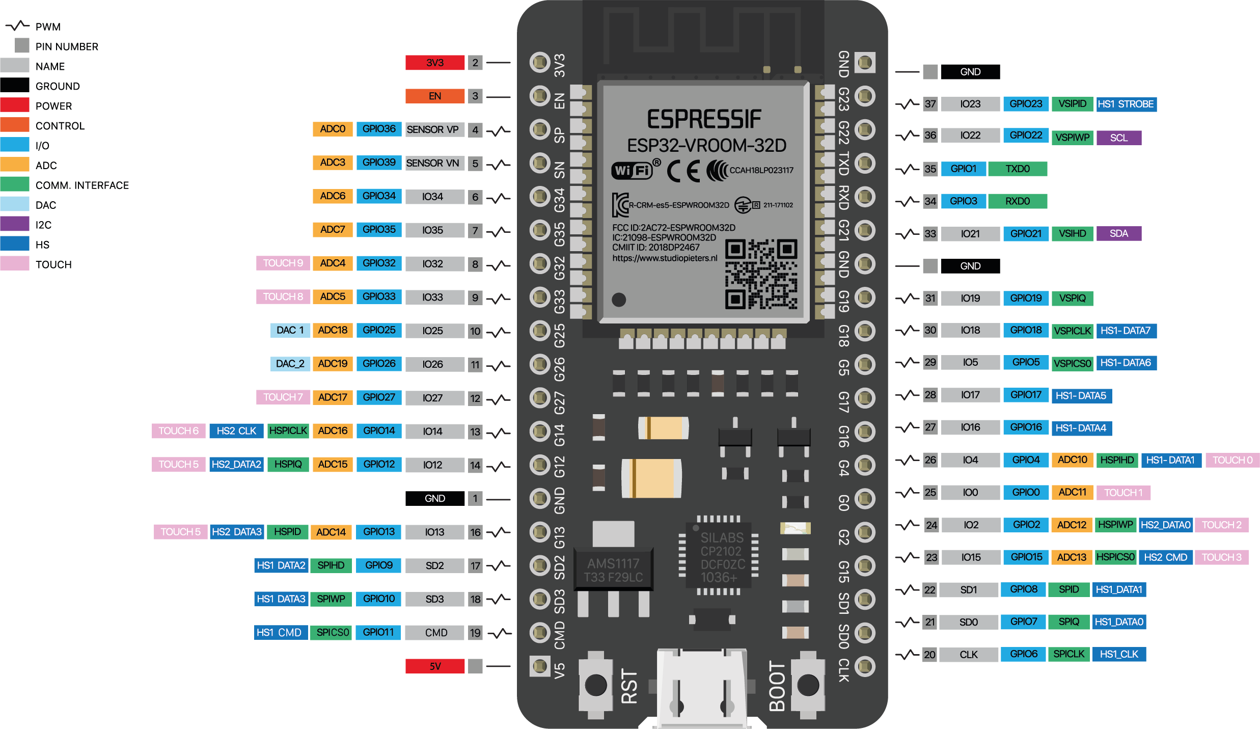
Note: Here, all the experiments are carried out using NodeMCU except that require bluetooth connectivity, where ESP32 is used. All the experiments can be done using ESP32. If you are using ESP32, check the arduino libraries in the code before compiling.
Introduction to Blynk
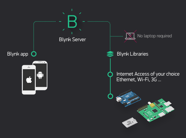
Blynk is a full suite of software required to prototype, deploy, and remotely manage connected electronic devices at any scale: from personal IoT projects to millions of commercial connected products. Blynk was designed for the Internet of Things. It can control hardware remotely, it can display sensor data, it can store data, vizualize it and do many other cool things. With Blynk anyone can connect their hardware to the cloud and build a no-code iOS, Android, and web applications to analyze real-time and historical data coming from devices, control them remotely from anywhere in the world, receive important notifications, and much more
Blynk works over the Internet. This means that the hardware you choose should be able to connect to the internet. Some of the boards, like Arduino Uno will need an Ethernet or Wi-Fi Shield to communicate, others are already Internet-enabled: like the ESP8266, ESP32, Raspberri Pi with WiFi dongle, Particle Photon or SparkFun Blynk Board.
Blynk: Setup
Introduction to Arduino IoT Cloud
The Arduino IoT Cloud is another platform that allows anyone to create IoT projects, with a user friendly interface, and an all in one solution for configuration, writing code, uploading and visualization. There is no need of installing Arduino IDE the Arduino code is run from the web itself with the help of a Arduino create agent which should be installed in the system. There is no need of including common libraries which is already included when the code is run from web.
Arduino IoT: Setup
Experiments
- LED Control using Blynk app
- LED Control using Arduino IoT Cloud
- Soil Moisture Sensor
- Light sensing using LDR Sensor
- Distance measuring using ultrasonic sensor
- Object Detection using IR sensor
- Bluetooth LED Control
- Bluetooth Bi-directional Communication
- Bluetooth Reliable Communication
- Realtime monitoring in FireBase
- Control using NodeRED through MQTT
LED Control using Blynk app
LED is made ON and OFF using a switch in the Blynk IoT cloud
Code
#define BLYNK_TEMPLATE_ID   "TMPLHdKB6u23"
#define BLYNK_DEVICE_NAME   "LED control"
#define BLYNK_AUTH_TOKEN    "GK0ilSKAGX1_fz0oAJOw8psfizAcbc2h"

#define BLYNK_PRINT Serial
#include <ESP8266WiFi.h>
#include <BlynkSimpleEsp8266.h>


char auth[] = BLYNK_AUTH_TOKEN;
char ssid[] = "m31";  // Wifi Username
char pass[] = "password";  // Wifi password

int ledpin = D4;  //connect LED +ve pin to D4 pin of NodeMCU
void setup()
{
  Serial.begin(115200);
  Blynk.begin(auth, ssid, pass);
  pinMode(ledpin,OUTPUT);
}

BLYNK_WRITE(V0) //LED control using virtual pin
{
  int value = param.asInt(); // Get value as integer
  digitalWrite(ledpin, value);}

void loop()
{
  Blynk.run();
}
Video
LED Control using Arduino IoT Cloud
LED is made ON and OFF using a switch in the Arduino IoT cloud
Code
/*
 The following variables are automatically generated and updated when changes are made to the Thing

  bool led_control;

*/

#include "thingProperties.h"

void setup() {
  // Initialize serial and wait for port to open:
  Serial.begin(9600);
  pinMode(D4, OUTPUT); //connect LED +ve pin to D4 pin of NodeMCU
  // This delay gives the chance to wait for a Serial Monitor without blocking if none is found
  delay(1500);

  // Defined in thingProperties.h
  initProperties();

  // Connect to Arduino IoT Cloud
  ArduinoCloud.begin(ArduinoIoTPreferredConnection);

  /*
     The following function allows you to obtain more information
     related to the state of network and IoT Cloud connection and errors
     the higher number the more granular information you’ll get.
     The default is 0 (only errors).
     Maximum is 4
 */
  setDebugMessageLevel(2);
  ArduinoCloud.printDebugInfo();
}

void loop()
{
  ArduinoCloud.update();
  // Our code here
}

/*
  Since LedControl is READ_WRITE variable, onLedControlChange() is
  executed every time a new value is received from IoT Cloud.
*/
void onLedControlChange()  //To control LED
{
  if (led_control == 1)
  {
    digitalWrite(D4, HIGH); //when switch ON
  }
  else
  {
    digitalWrite(D4, LOW); //when switch OFF
  }
}
Video
Soil Moisture Sensor
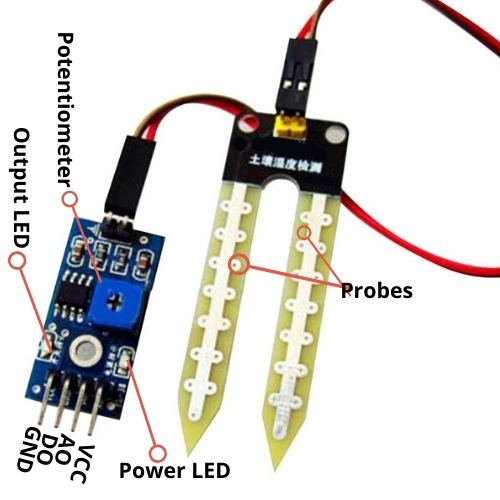
The soil moisture sensor measures the water content of the soil when their probes are inserted in the soil.
In this experiment, the analog sensor data from the sensor is displayed in the Arduino IoT cloud. The sensitivity of the sensor can be adjusted by varying the potentiometer on the module.
Code
/*
  The following variables are automatically generated and updated when changes are made to the Thing

  int soil_val;

*/

#include "thingProperties.h"

void setup() {
  // Initialize serial and wait for port to open:
  Serial.begin(9600);
  pinMode(A0,INPUT); //connect AO to A0 pin of NodeMCU
  // This delay gives the chance to wait for a Serial Monitor without blocking if none is found
  delay(1500);

  // Defined in thingProperties.h
  initProperties();

  // Connect to Arduino IoT Cloud
  ArduinoCloud.begin(ArduinoIoTPreferredConnection);

  setDebugMessageLevel(2);
  ArduinoCloud.printDebugInfo();
}

void loop() {
  ArduinoCloud.update();
  soil_val=analogRead(A0);
  Serial.println(soil_val);
}
Video
Light sensing using LDR Sensor
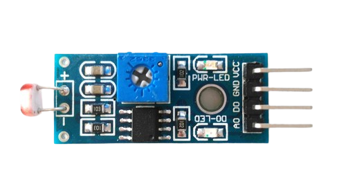
The LDR (Light Depndant Resistor) is a passive component that decreases resistance with respect to receiving luminosity (light) on the component’s sensitive surface. The resistance of a photoresistor decreases with increase in incident light intensity, i.e, it exhibits photoconductivity.n the dark, a photoresistor can have a resistance as high as several megaohms (MΩ), while in the light, a photoresistor can have a resistance as low as a few hundred ohms.
In this experiment, the data from the sensor is displayed in the Arduino IoT cloud. The sensitivity of the sensor can be adjusted by varying the potentiometer on the module.
Code
/*
  The following variables are automatically generated and updated when changes are made to the Thing

  int ldr_val;

*/

#include "thingProperties.h"

void setup() {
  // Initialize serial and wait for port to open:
  Serial.begin(9600);
  pinMode(A0,INPUT); //connect AO pin of LDR to A0 pin of NodeMCU
  // This delay gives the chance to wait for a Serial Monitor without blocking if none is found
  delay(1500);

  // Defined in thingProperties.h
  initProperties();

  // Connect to Arduino IoT Cloud
  ArduinoCloud.begin(ArduinoIoTPreferredConnection);

  setDebugMessageLevel(2);
  ArduinoCloud.printDebugInfo();
}

void loop() {
  ArduinoCloud.update();
  ldr_val=analogRead(A0);
  Serial.println(ldr_val);
  delay(500);
}
Video
Distance measuring using Ultrasonic sensor
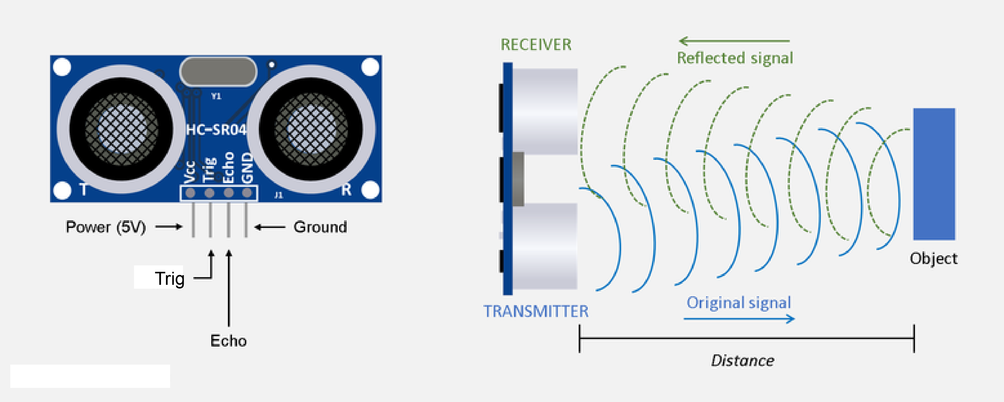
An ultrasonic sensor is an electronic device that measures the distance of a target object by emitting ultrasonic sound waves, and converts the reflected sound into an electrical signal. Ultrasonic waves travel faster than the speed of audible sound (i.e. the sound that humans can hear). Ultrasonic sensors have two main components: the transmitter (which emits the sound using piezoelectric crystals) and the receiver (which encounters the sound after it has travelled to and from the target). Here, the HC-SR04 ultrasonic sensor is used which has an echo (input pin) and a trigger pin (output pin) for recieving and transmitting pulses respectively.
In order to calculate the distance between the sensor and the object, the sensor measures the time it takes between the emission of the sound by the transmitter to its contact with the receiver. The formula for this calculation is D = ½ T x C (where D is the distance, T is the time, and C is the speed of sound ~ 343 meters/second). The range of the sensor is 2cm to 400cm and emits a high-frequency of 40Khz.
In this experiment, the distance measured by the ultrasonic sensor is displayed in the Arduino IoT cloud.
Code
/*
  The following variables are automatically generated and updated when changes are made to the Thing

  float distance;

*/

#include "thingProperties.h"

int trig=D0; //connect trig to D0 pin of NodeMCU
int echo=D1; //connect echo to D1 pin of NodeMCU
float duration;


void setup() {
  // Initialize serial and wait for port to open:
  Serial.begin(9600);
  pinMode(echo,INPUT);
  pinMode(trig,OUTPUT);
  // This delay gives the chance to wait for a Serial Monitor without blocking if none is found
  delay(1500);

  // Defined in thingProperties.h
  initProperties();

  // Connect to Arduino IoT Cloud
  ArduinoCloud.begin(ArduinoIoTPreferredConnection);

  setDebugMessageLevel(2);
  ArduinoCloud.printDebugInfo();
}

void loop() {
  ArduinoCloud.update();

  digitalWrite(trig, LOW);delayMicroseconds(2); //for a clean pulse
  digitalWrite(trig,HIGH);delayMicroseconds(100);digitalWrite(trig,LOW); //send pulses for 100μs
  duration=pulseIn(echo,HIGH); //time to recieve the pulse
  distance=duration*(0.0340/2.0); //distance calculation
  Serial.println(distance);
}
Video
Object Detection using IR sensor
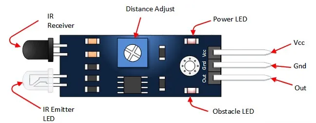
This is a multipurpose infrared sensor which can be used for obstacle sensing, color detection(between basic contrasting colors), fire detection, line sensing, etc and also as an encoder sensor. The sensor provides a digital output. The sensor outputs a logic one(+5V) at the digital output when an object is placed in front of the sensor and a logic zero(0V), when there is no object in front of the sensor. An on board LED is used to indicate the presence of an object.
The onboard potentiometer is used to calibrate the sensor. To set the potentiometer, use a screw driver and turn the potentiometer, till the output LED just turns off.
In this experiment, when an object is detected by the IR sensor, a red light glows as an indication in the Arduino IoT cloud and otherwise, green light glows.
Code
/*
  The following variables are automatically generated and updated when changes are made to the Thing

  bool ir;

*/

#include "thingProperties.h"

void setup() {
  // Initialize serial and wait for port to open:
  Serial.begin(9600);
  pinMode(D0,INPUT);
  // This delay gives the chance to wait for a Serial Monitor without blocking if none is found
  delay(1500);

  // Defined in thingProperties.h
  initProperties();

  // Connect to Arduino IoT Cloud
  ArduinoCloud.begin(ArduinoIoTPreferredConnection);

  setDebugMessageLevel(2);
  ArduinoCloud.printDebugInfo();
}

void loop() {
  ArduinoCloud.update();

  ir=digitalRead(D0);
  if (digitalRead(D0)==1)
  {
    ir=digitalRead(D0);
  }
}
Video
Introduction to MIT App Inventor

MIT App Inventor is a web application integrated development environment originally provided by Google, and now maintained by the Massachusetts Institute of Technology (MIT). It allows newcomers to computer programming to create application software (apps). It uses a graphical user interface (GUI) very similar to the programming languages Scratch (programming language) and the StarLogo, which allows users to drag and drop visual objects.
Note: The following codes for bluetooth communication will only work on Android. The reason is that BluetoothSerial does not work on an Iphone. For an Iphone only BLE works. So they are only for Android apps.
Bluetooth LED control
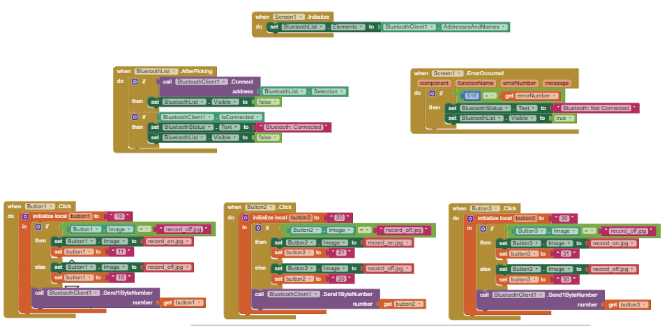
In this experiment, three LEDs are controlled using three different buttons in the app developed in the MIT app inventor. The ESP32 is used for achieving the bluetooth communication.
Code
// --------------------------------------------------
//
// Code for control of ESP32 through MIT inventor app (Bluetooth).
// device used for tests: ESP32-WROOM-32D
//
// App on phone has three buttons:
// Button 1: 11 for ON and 10 for OFF
// Button 2: 21 for ON and 20 for OFF
// Button 3: 31 for ON and 30 for OFF
//
// --------------------------------------------------

// this header is needed for Bluetooth Serial -> works ONLY on ESP32
#include "BluetoothSerial.h"

// init Class:
BluetoothSerial ESP_BT;

// init PINs: assign any pin on ESP32
int led_pin_1 = 5;
int led_pin_2 = 18;
int led_pin_3 = 19;

// Parameters for Bluetooth interface
int incoming;

void setup() {
  Serial.begin(19200);
  ESP_BT.begin("ESP32_Control"); //Name of your Bluetooth interface -> will show up on your phone

  pinMode (led_pin_1, OUTPUT);
  pinMode (led_pin_2, OUTPUT);
  pinMode (led_pin_3, OUTPUT);
}

void loop() {

  // -------------------- Receive Bluetooth signal ----------------------
  if (ESP_BT.available())
  {
    incoming = ESP_BT.read(); //Read what we receive

    // separate button ID from button value -> button ID is 10, 20, 30, etc, value is 1 or 0
    int button = floor(incoming / 10);
    int value = incoming % 10;

    switch (button) {
      case 1:
        Serial.print("Button 1:"); Serial.println(value);
        digitalWrite(led_pin_1, value);
        break;
      case 2:
        Serial.print("Button 2:"); Serial.println(value);
        digitalWrite(led_pin_2, value);
        break;
      case 3:
        Serial.print("Button 3:"); Serial.println(value);
        digitalWrite(led_pin_3, value);
        break;
    }
  }
}
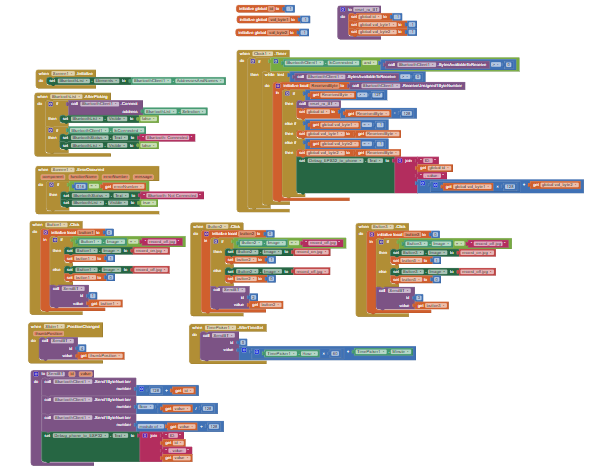
For the MIT App Inventor code, download: MIT App code
For detailed explanation, watch the video: Bluetooth LED Control
A screenshot of the code block is provided below:
Video
Bluetooth Bi-directional Communication
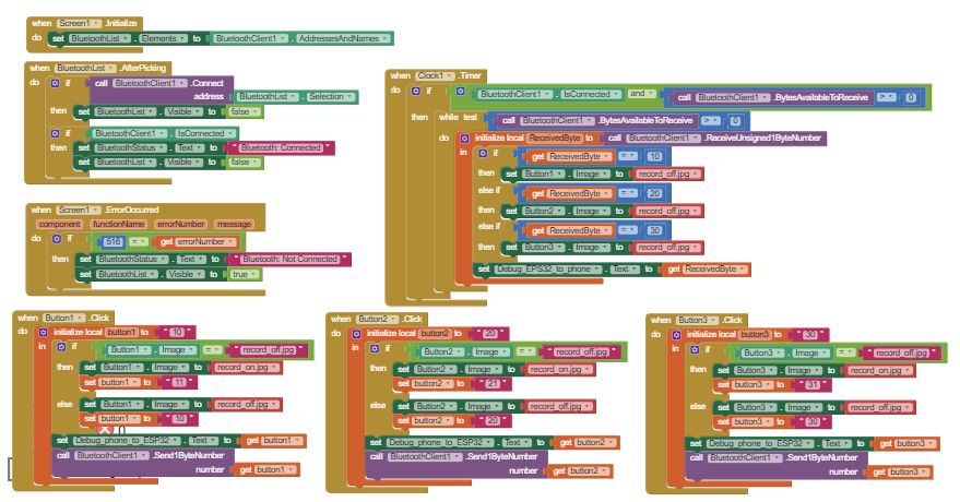
In addition to the previous experiment, bi-directional communication is employed in this experiment. Here, we can write values from ESP32 to the app. Also, the led will turn off after 1 second when its turned ON.
Code
// --------------------------------------------------
//
// ESP32 Bluetooth App part 2 -> bi-directional cummunication
//
// Code for bi-directional Bluetooth communication demonstration between the ESP32 and mobile phone (with MIT inventor app).
// device used for tests: ESP32-WROOM-32D
//
// App on phone has three buttons. Each button switches on a port on the ESP32.
// After 1 second the ESP32 switches off the buttons on the phone.
// Communication between phone and ESP32 is as follows:
// Button 1: 11 for ON and 10 for OFF
// Button 2: 21 for ON and 20 for OFF
// Button 3: 31 for ON and 30 for OFF
//
// --------------------------------------------------

// this header is needed for Bluetooth Serial -> works ONLY on ESP32
#include "BluetoothSerial.h"

// definition of the delaytime between button on and button off
#define DELAY 1000                      // delay is in milliseconds, so 1000ms corresponds to 1s

// init Class:
BluetoothSerial ESP_BT;

// init PINs: assign any pin on ESP32
int led_pin_1 = 5;
int led_pin_2 = 18;
int led_pin_3 = 19;

// Parameters for Bluetooth interface and timing
int incoming;                           // variable to store byte received from phone
unsigned long now;                      // variable to store current "time" using millis() function
unsigned long time_button1;             // timestamp for button1 to 3 -> stores time when button is enabled
unsigned long time_button2;
unsigned long time_button3;

void setup() {
  Serial.begin(19200);
  ESP_BT.begin("ESP32_Control");        // Name of your Bluetooth interface -> will show up on your phone

  pinMode (led_pin_1, OUTPUT);          // Define output ports to connect LEDs
  pinMode (led_pin_2, OUTPUT);
  pinMode (led_pin_3, OUTPUT);
}

void loop() {
  now = millis();                       // Store current time

  // time-out check -> check if a button is on and whether it needs to be switched off
  if(digitalRead(led_pin_1) and now > time_button1 + DELAY) {     // if output port (led_pin_1) is active and if the delay time has passed, the button is to be switched off
    digitalWrite(led_pin_1, 0);                                   // set output port to 0
    ESP_BT.write(10);                                             // send byte to phone indicateding that Button 1 is to be set to 0 -> 10
    Serial.println("Button 1 timeout - value: 0");                  // write to serial port for easy debugging
  }
  if(digitalRead(led_pin_2) and now > time_button2 + DELAY) {
    digitalWrite(led_pin_2, 0);
    ESP_BT.write(20);                                             // send byte to phone indicateding that Button 2 is to be set to 0 -> 20
    Serial.println("Button 2 timeout - value: 0");
  }
  if(digitalRead(led_pin_3) and now > time_button3 + DELAY) {
    digitalWrite(led_pin_3, 0);
    ESP_BT.write(30);                                             // send byte to phone indicateding that Button 3 is to be set to 0 -> 30
    Serial.println("Button 3 timeout - value: 0");
  }

  // -------------------- Receive Bluetooth signal ----------------------
  if (ESP_BT.available())
  {
    incoming = ESP_BT.read(); //Read what we receive and store in "incoming"

    // separate button ID from button value -> button ID is 10, 20, 30, etc, value is 1 or 0
    int button = floor(incoming / 10);
    int value = incoming % 10;

    switch (button) {
      case 1:
        Serial.print("Button 1:"); Serial.println(value);
        digitalWrite(led_pin_1, value);
        if(value == 1)                                            // check if the button is switched on
          time_button1 = now;                                     // if button is switched on, write the current time to the timestamp
        break;
      case 2:
        Serial.print("Button 2:"); Serial.println(value);
        digitalWrite(led_pin_2, value);
        if(value == 1)
          time_button2 = now;
        break;
        case 3:
        Serial.print("Button 3:"); Serial.println(value);
        digitalWrite(led_pin_3, value);
        if(value == 1)
          time_button3 = now;
        break;
    }
  }
}
For detailed explanation, watch the video: Bluetooth Bi-directional communication
For the MIT App Inventor code, download: MIT App code
A screenshot of the code block is provided below:
Video
Bluetooth Reliable Communication
In the previous experiments, we have to transmit only single byte values(0-255 values). In this experiment, multiple bytes are transmitted bidirectionally. Here, LEDs are not necessary since only communication is verified in the serial monitor.
Code
// --------------------------------------------------
//
// ESP32 Bluetooth App part 3 -> reliable cummunication of id and value
//
// Code for reliable communication between the ESP32 and mobile phone (with MIT inventor app).
// device used for tests: ESP32-WROOM-32D
//
// Data is sent in 3 bytes:
// First byte is the identification byte -> values used 128 - 255
// Second byte is the most significant byte of the data -> values used 0 - 127
// Third byte is the least significant byte of the data -> values used 0 - 127
//
// --------------------------------------------------

// this header is needed for Bluetooth Serial -> works ONLY on ESP32
#include "BluetoothSerial.h"

// init Class:
BluetoothSerial ESP_BT;

// Parameters for Bluetooth interface and timing
int incoming;                           // variable to store byte received from phone
int id = -1;                            // received identification byte
int val_byte1 = -1;                     // most significant byte of data value
int val_byte2 = -1;                     // least significant byte of data value

void setup() {
  Serial.begin(19200);
  ESP_BT.begin("ESP32_Control");        // Name of your Bluetooth interface -> will show up on your phone

}

void loop() {

  // -------------------- Receive Bluetooth signal ----------------------
  if (ESP_BT.available())
  {
    incoming = ESP_BT.read();           // Read what we receive and store in "incoming"

    if (incoming > 127) {               // ID bytes are 128 or higher, so check if incoming byte is an ID-byte
      reset_rx_BT();                    // reset id and data to -1
      id = incoming - 128;              // write id value
    }
    else if (val_byte1 == -1) {         // if incoming byte is lower than 128 it is a data byte. Check if first data byte is empty (-1)
      val_byte1 = incoming;             // write first data byte (MSB)
    }
    else if (val_byte2 == -1) {         // check if second data byte is empty (-1)
      val_byte2 = incoming;             // write second data byte (LSB)
      int value = 128*val_byte1 + val_byte2;          // recombine the first and second data byte to the actual value that was sent from the phone
      // here is the location that you can implement the code what you want to do with the controller id and value received from the phone

      Serial.print("Id: "); Serial.print(id); Serial.print(", val: "); Serial.println(value);   // for debugging write to the serial interface (check with serial monitor)
      send_BT(id, value);               // for test purposes we just send the data back to the phone
      reset_rx_BT();                    // not strictly needed, but just in case erase all bytes (set to -1)
    }
  }
}

void reset_rx_BT() {                    // function to erase all bytes (set to -1)
  id = -1;
  val_byte1 = -1;
  val_byte2 = -1;
}
void send_BT(int id, int value) {       // function to write id and value to the bluetooth interface (and split value in MSB and LSB
  ESP_BT.write(128 + id);
  ESP_BT.write(floor(value/128));       // MSB
  ESP_BT.write(value%128);              // LSB
}
For detailed explanation, watch the video: Bluetooth Reliable communication
For the MIT App Inventor code, download: MIT App code
A screenshot of the code block is provided below:
Video
Introduction to Firebase

Firebase is a platform developed by Google for creating mobile and web applications. It was originally an independent company founded in 2011. In 2014, Google acquired the platform and it is now their flagship offering for app development. Realtime data monitoring can be achieved through Firebase using the realtime database or the cloud firestore.
Realtime monitoring in Firebase
In this experiment, the real-time value of the potentiometer is send to the Firebase console through the NodeMCU.
For this experiment, some settings should be made in the Firebase account. Follow this tutorial for the complete guidance: Firebase setup
Code
//This code can be used for ESP32 and NodeMCU
#include <Arduino.h>
#if defined(ESP32)
  #include <WiFi.h>
#elif defined(ESP8266)
  #include <ESP8266WiFi.h>
#endif
#include <Firebase_ESP_Client.h>

//Provide the token generation process info.
#include "addons/TokenHelper.h"
//Provide the RTDB payload printing info and other helper functions.
#include "addons/RTDBHelper.h"

// Insert your network credentials
#define WIFI_SSID "Tenda_EXT"
#define WIFI_PASSWORD "Shivajyothi2000"

// Insert Firebase project API Key
#define API_KEY "AIzaSyArEGYFkxfqmYYlYtXsr3K_RgwQtA8fMZg"

// Insert RTDB URLefine the RTDB URL */
#define DATABASE_URL "https://nodemcu-41d68-default-rtdb.firebaseio.com/"

//Define Firebase Data object
FirebaseData fbdo;

FirebaseAuth auth;
FirebaseConfig config;

unsigned long sendDataPrevMillis = 0;
bool signupOK = false;
int pot;

void setup(){
  Serial.begin(115200);
  WiFi.begin(WIFI_SSID, WIFI_PASSWORD);
  Serial.print("Connecting to Wi-Fi");
  while (WiFi.status() != WL_CONNECTED){
    Serial.print(".");
    delay(300);
  }
  Serial.println();
  Serial.print("Connected with IP: ");
  Serial.println(WiFi.localIP());
  Serial.println();

  /* Assign the api key (required) */
  config.api_key = API_KEY;

  /* Assign the RTDB URL (required) */
  config.database_url = DATABASE_URL;

  /* Sign up */
  if (Firebase.signUp(&config, &auth, "", "")){
    Serial.println("ok");
    signupOK = true;
  }
  else{
    Serial.printf("%s\n", config.signer.signupError.message.c_str());
  }

  /* Assign the callback function for the long running token generation task */
  config.token_status_callback = tokenStatusCallback; //see addons/TokenHelper.h

  Firebase.begin(&config, &auth);
  Firebase.reconnectWiFi(true);
}

void loop()\
{
       pot=analogRead(A0);
       Serial.println(pot);
       Firebase.RTDB.setInt(&fbdo, "Potentiometer", pot);  // Write the potentiometer value on the database path pot

    /* For writing a float value, replace the "setInt" with "setFloat
       Eg: Firebase.RTDB.setFloat(&fbdo, "test/int", count); */
}
Video
Introduction to MQTT protocol and Node-Red
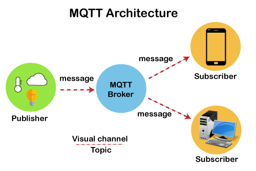
MQTT (Message Queue Telemetry Transport) is an OASIS standard messaging protocol for the Internet of Things (IoT). It is designed as an extremely lightweight publish/subscribe messaging transport that is ideal for connecting remote devices with a small code footprint and minimal network bandwidth. MQTT today is used in a wide variety of industries, such as automotive, manufacturing, telecommunications, oil and gas, etc.
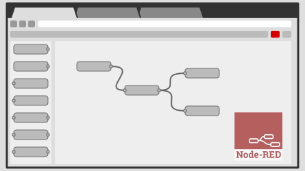
Node-RED is a flow-based development tool for visual programming developed originally by IBM for wiring together hardware devices, APIs and online services as part of the Internet of Things.
Node-RED uses MQTT communication protocol and provides a web browser-based flow editor, which can be used to create JavaScript functions. Elements of applications can be saved or shared for re-use. The runtime is built on Node.js. The flows created in Node-RED are stored using JSON. Since version 0.14, MQTT nodes can make properly configured TLS connections.
For detailed information: MQTT site::::MQTT video


